ESP32のPWMとDACを使ってみる ~ おまけ:LCDのバックライトを調光
サクサクと動かす事が出来た1.3インチLCDですが、今回はバックライトを調光しようと思います。
小さい画面ですからたいして眩しく無いんですけれど、ESP32はArduinoの様なAnalogWrite関数が無いらしいですね。
代わりにLED制御用の関数 ledc というのがあるらしく、これがESP32ではPWM出力用として使われる様です。
はて、確かESP32はDACも持ってなかったっけ・・・?
というわけで調べたら25、26番ピンがアナログ波形を出力できるみたいですね。
dacWriteというメソッドで実行できる様子。
ひとまずいきなりLCDのバックライトを操作するのは怖いですので、LEDで試みてみます。
ESP32 PWM(ledc)によるLEDの調光制御
EspressifのArduino core for the ESP32ライブラリを使ってみます。
検索をかけてみると、それらしきものがありました。
毎度の事ながらヘッダーしか見ませんが・・・
一部抜粋
//channel 0-15 resolution 1-16bits freq limits depend on resolution
https://github.com/espressif/arduino-esp32/blob/master/cores/esp32/esp32-hal-ledc.h
double ledcSetup(uint8_t channel, double freq, uint8_t resolution_bits);
void ledcWrite(uint8_t channel, uint32_t duty);
double ledcWriteTone(uint8_t channel, double freq);
double ledcWriteNote(uint8_t channel, note_t note, uint8_t octave);
uint32_t ledcRead(uint8_t channel);
double ledcReadFreq(uint8_t channel);
void ledcAttachPin(uint8_t pin, uint8_t channel);
void ledcDetachPin(uint8_t pin);
これを見ると0~15の合計16チャンネルを持つ事が出来て、各チャンネルに登録されたGPIOに対して制御できる様な造りになっている様子。
PWM的なものって出すだけかと思ってましたが、なかledcRead系のものもある様で。
PWMを読み取れるって事なんでしょうか。
モールス信号的な?
よく判らないのでRead系はとりあえずスルーしておいて、、
ledcの使い方
1.ledcSetup でチャンネルと周波数、ビット幅を決める
2.ledcAttachPin でPWMを出力するGPIOピンとチャンネルを関連づける
3.ledcWrite でチャンネルに対してデューティー比を指定して出力する
こんな感じかな。
わりと簡潔に出来ている様です。
コードはこんな感じでしょうか。
#include <Arduino.h>

// PWM出力 ledc変数
uint8_t ledcGPIO = 27;		// PWM GPIO
uint8_t ledcCH = 0;			// ledcチャンネル
double ledcFreq = 5000;		// PWM周波数
uint8_t ledcBitWidth = 8;	// 8bit 0-255(13bit default)
uint32_t ledcDuty = ( pow(2, ledcBitWidth) / 2 ) - 1;	// デューティ比初期値設定 1/2 (127)

uint16_t timeWait = 2;		// 調光ウェイト ms

void setup() {
	Serial.begin(115200);

	// 1.ledc設定
	ledcSetup(ledcCH, ledcFreq, ledcBitWidth);

	// 2.GPIOピンをチャンネルに所属させる
	ledcAttachPin(ledcGPIO, ledcCH);

	// 3.対象チャンネルに対してデューティ値(ビット幅分の値)でPWM開始
	ledcWrite(ledcCH, ledcDuty);

	// 比較用LED 常灯
	pinMode(14, OUTPUT);
	digitalWrite(14, HIGH);

}

// デューティー比増減
void volumeDuty(void *param) {

	Serial.println("volumeDuty Start.");

	for(uint8_t cnt = 0; cnt < 5; cnt++) {
		for(long i=0; i <= pow(2, ledcBitWidth)-1; i++) {
			ledcWrite(ledcCH, i);
			delay(timeWait);
			Serial.print("LEDC Duty : ");
			Serial.println(i);
		}
		for(long i=pow(2, ledcBitWidth)-1; i >= 0; i--) {
			ledcWrite(ledcCH, i);
			delay(timeWait);
			Serial.print("LEDC Duty : ");
			Serial.println(i);
		}
	}

	Serial.println("volumeDuty End.");
	ledcWrite(ledcCH, 0);
}

void loop() {
	volumeDuty(NULL);
}
8bitの分解能は0-255の256値ですから、とりあえず初期値は適当に半分にして点灯させてみます。
その後メインループで0-255の間を繰り返し増減させています。
大体リニアに明るさが変化している感じですね。
pwm周波数が5000との事で、要するに1秒間に5000回更新されています。
これのデューティ比1/2という事は、1秒間の間に2500回OFFし2500回ONしているという計算。
全くチラつきは感じません。
実際チラつくとどうなるのかが気になりましたので、周波数を落としてみました。
人間の目は30Hz~50Hzくらいまでは感知できるらしいのですが、肉眼ではキッチリと50Hzでチラつきは見えなくなりました。
私の目は人並みという事か
しかし動画では多少はチラついて見える事から、実際にはちゃんと点滅しているのでしょう。
また、チラついている様な低周波数の時でもDuty比が1:1に近ければほぼ常灯している事から、ちゃんとPWMで出力されているんだなという事が想像できます。
オシロスコープでも持ってれば見る事が出来るのでしょうけれど・・・
さて次にDACによるコントロールを見ていきます。
ESP32 DAC(dacWrite)によるLEDの調光制御
ヘッダを見るとこちらは至極簡単で、そのまま0-255のレベルの範囲で出力できる様です。
DACに使えるGPIOピンが25,26と限られている様ですが、お手軽で良いですね。
簡単にコードに追加してみます。
#include <Arduino.h>

// PWM出力 ledc変数
uint8_t ledcGPIO = 27;		// PWM GPIO
uint8_t ledcCH = 0;			// ledcチャンネル
double ledcFreq = 5000;		// PWM周波数
uint8_t ledcBitWidth = 8;	// 8bit 0-255(13bit default)
uint32_t ledcDuty = ( pow(2, ledcBitWidth) / 2 ) - 1;	// デューティ比初期値設定 1/2 (127)

uint8_t dacGPIO = 26;		// DAC GPIO

uint16_t timeWait = 3;		// 調光ウェイト ms (vtaskの時はtick)

void setup() {
	Serial.begin(115200);

	// 1.ledc設定
	ledcSetup(ledcCH, ledcFreq, ledcBitWidth);

	// 2.GPIOピンをチャンネルに所属させる
	ledcAttachPin(ledcGPIO, ledcCH);

	// 3.対象チャンネルに対してデューティ値(ビット幅分の値)でPWM開始
	ledcWrite(ledcCH, ledcDuty);

	ledcFreq = 0;
	ledcWrite(ledcCH, 0);

	// 比較用LED 常灯
	pinMode(14, OUTPUT);
	digitalWrite(14, HIGH);

	// 比較用LED DAC
	pinMode(dacGPIO, OUTPUT);
	dacWrite(dacGPIO, 0);
}

// デューティー比増減
void volumeDuty(void *param) {

	Serial.println("volumeDuty Start.");

	for(uint8_t cnt = 0; cnt < 5; cnt++) {

		for(long i=0; i <= pow(2, ledcBitWidth)-1; i++) {
			ledcWrite(ledcCH, i);
			dacWrite(dacGPIO, i);
			delay(timeWait);
			Serial.print("LEDC DAC Duty : ");
			Serial.println(i);
		}
		for(long i=pow(2, ledcBitWidth)-1; i >= 0; i--) {
			ledcWrite(ledcCH, i);
			dacWrite(dacGPIO, i);
			delay(timeWait);
			Serial.print("LEDC DAC Duty : ");
			Serial.println(i);
		}
	}

	Serial.println("volumeDuty End.");
	ledcWrite(ledcCH, 0);
	dacWrite(dacGPIO, 0);
}

void loop() {
	volumeDuty(NULL);
}
こんな感じでPWMのデューティー比と一緒に動かしてみます。
PWMの方はデューティー比が低い時でも僅かに点灯するのに対し、DACの方は途中からしか光りだしません。
これはダイオードであるLEDの性質上、電圧がある程度高く無いと電流が流れない事に起因するのだと推測。
つまりPWMの方は、一瞬の3.29Vを細かく出している為に微量の電流は流れるのに対し、DACは0Vから徐々に上げていくのでダイオードを通過できる電圧になるまで電流が流れないという事かしら?
というわけでテスターで電圧の様子を計測。
更新サイクル秒間3回のTDX-200で何とか計れる様に100msのディレイを入れました。
んん、DAC側は2.28V辺りまで点灯しませんでした。
はじめから電流を計ればよかったのではというのはさて置いて
・・・ちゃんと電流も計りましたYo
2.28Vから1uA(0.001mA)流れ始めたのを観測。(動画はとってません)
凄いですね、、、僅かとはいえ、LEDって1uAで光るんスね・・・
まぁなんか寄り道し過ぎましたが、、、
本題のLCDのバックライトの調光をしてみます。
LCD バックライトの調光
LEDの明るさをリニアに調整するにはDAC出力よりもPWM制御が向いていそうでしたので、先日使用したLCDのBLK端子に接続したGPIOをPWMで制御してやります。
このピンの入電が本当にバックライトをON/OFFできるのか謎ですが、、
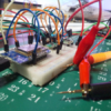
そして配線はいつもの如く、酷く乱暴な感じで・・・
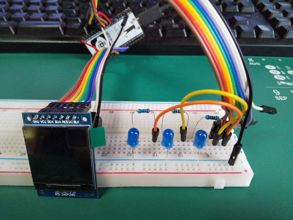
ソースは貼っておきますが、一部な事、TFT_eSPIライブラリを使っている事から折りたたみで・・・
// 'Boing' ball demo

// STM32F767 55MHz SPI 170 fps without DMA
// STM32F767 55MHz SPI 227 fps with DMA
// STM32F446 55MHz SPI 110 fps without DMA
// STM32F446 55MHz SPI 187 fps with DMA
// STM32F401 55MHz SPI  56 fps without DMA
// STM32F401 55MHz SPI 120 fps with DMA

// STM32F767 27MHz SPI  99 fps without DMA
// STM32F767 27MHz SPI 120 fps with DMA
// STM32F446 27MHz SPI  73 fps without DMA
// STM32F446 27MHz SPI  97 fps with DMA
// STM32F401 27MHz SPI  51 fps without DMA
// STM32F401 27MHz SPI  90 fps with DMA

// Blue Pill - 36MHz SPI *no* DMA 36 fps
// Blue Pill - 36MHz SPI with DMA 67 fps
// Blue Pill overclocked to 128MHz *no* DMA - 32MHz SPI  64 fps
// Blue Pill overclocked to 128MHz with DMA - 32MHz SPI 116 fps

// ESP32     - 8 bit parallel     110 fps (no DMA)
// ESP32     - 40MHz SPI *no* DMA  93 fps
// ESP32     - 40MHz SPI with DMA 112 fps

#define SCREENWIDTH 320
#define SCREENHEIGHT 240
// BMP横サイズがでかいのでエラーが出ちゃう
//define SCREENWIDTH 240
//#define SCREENHEIGHT 240

#include <TFT_eSPI.h> // Hardware-specific library

// 追加
#include <TJpg_Decoder.h>
#include "graphic.h"

TFT_eSPI tft = TFT_eSPI();       // Invoke custom library

#define BGCOLOR    0xAD75
#define GRIDCOLOR  0xA815
#define BGSHADOW   0x5285
#define GRIDSHADOW 0x600C
#define RED        0xF800
#define WHITE      0xFFFF

#define YBOTTOM  123  // Ball Y coord at bottom
#define YBOUNCE -3.5  // Upward velocity on ball bounce

// Ball coordinates are stored floating-point because screen refresh
// is so quick, whole-pixel movements are just too fast!
float ballx     = 20.0, bally     = YBOTTOM, // Current ball position
      ballvx    =  0.8, ballvy    = YBOUNCE, // Ball velocity
      ballframe = 3;                         // Ball animation frame #
int   balloldx  = ballx, balloldy = bally;   // Prior ball position

// Working buffer for ball rendering...2 scanlines that alternate,
// one is rendered while the other is transferred via DMA.
uint16_t renderbuf[2][SCREENWIDTH];

uint16_t palette[16]; // Color table for ball rotation effect

uint32_t startTime, frame = 0; // For frames-per-second estimate

// PWM出力 ledc変数
uint8_t ledcGPIO = 27;		// PWM GPIO
uint8_t ledcCH = 0;			// ledcチャンネル
double ledcFreq = 5000;		// PWM周波数
uint8_t ledcBitWidth = 8;	// 8bit 0-255(13bit default)
uint32_t ledcDuty = ( pow(2, ledcBitWidth) / 2 ) - 1;	// デューティ比初期値設定 1/2 (127)

// LCD バックライト用GPIO
uint8_t LCDGPIO = 4;		// LCD GPIO

// DAC用GPIO
uint8_t dacGPIO = 26;		// DAC GPIO

uint16_t timeWait = 5;		// 調光ウェイト ms (vtaskの時はtick)

// タスクハンドラ
TaskHandle_t pBehindTask;
// タスク関数
void volumeDuty(void *);
void behindPollingSerial(void *);

void setup() {
  Serial.begin(115200);
//  while(!Serial);

	// 1.ledc設定
	ledcSetup(ledcCH, ledcFreq, ledcBitWidth);
	// 2.GPIOピンをチャンネルに所属させる
	ledcAttachPin(ledcGPIO, ledcCH);
	ledcAttachPin(LCDGPIO, ledcCH);
	// 3.対象チャンネルに対してデューティ値(ビット幅分の値)でPWM開始
	ledcWrite(ledcCH, ledcDuty);

	// 比較用LED 通常
	pinMode(14, OUTPUT);
	digitalWrite(14, HIGH);

	// 比較用LED DAC
	pinMode(dacGPIO, OUTPUT);
	dacWrite(dacGPIO, ledcDuty);


  tft.begin();
  tft.setRotation(3); // Landscape orientation, USB at bottom right
  tft.setSwapBytes(false);
  // Draw initial framebuffer contents:
  //tft.setBitmapColor(GRIDCOLOR, BGCOLOR);
  tft.fillScreen(BGCOLOR);

  tft.initDMA();

  tft.drawBitmap(0, 0, (const uint8_t *)background, SCREENWIDTH, SCREENHEIGHT, GRIDCOLOR);

  startTime = millis();
}

// デューティー比増減
void volumeDuty(void *param) {

	Serial.println("volumeDuty Start.");

	for(uint8_t cnt = 0; cnt < 10; cnt++) {
		for(long i=0; i <= pow(2, ledcBitWidth)-1; i++) {
			ledcWrite(ledcCH, i);
			dacWrite(dacGPIO, i);
//			delay(timeWait);
			vTaskDelay(timeWait);
			Serial.print("LEDC,DAC,LCD Duty param: ");
			Serial.println(i);
		}
		for(long i=pow(2, ledcBitWidth)-1; i >= 0; i--) {
			ledcWrite(ledcCH, i);
			dacWrite(dacGPIO, i);
//			delay(timeWait);
			vTaskDelay(timeWait);
			Serial.print("LEDC,DAC,LCD Duty param: ");
			Serial.println(i);
		}
	}

	Serial.println("volumeDuty End.");
	ledcWrite(ledcCH, ledcDuty);
	dacWrite(dacGPIO, ledcDuty);

	// one shot タスクなので自爆終了
	vTaskDelete(NULL);
}

void loop() {

	// コマンド待ち受け
	if (Serial.available())
	{
		int inputchar = Serial.read();
		if (char(inputchar) == '@')
		{
			// 輝度調整ワンショット
			xTaskCreatePinnedToCore(
				volumeDuty,				//	TaskFunction_t pvTaskCode,
				"volumeDuty",			//	const char * const pcName,
				2048,					//	const uint32_t usStackDepth,
				NULL,					//	void * const pvParameters,
				1,						//	UBaseType_t uxPriority,
				&pBehindTask,			//	TaskHandle_t * const pvCreatedTask,
				0);
		}
	}


  balloldx = (int16_t)ballx; // Save prior position
  balloldy = (int16_t)bally;
  ballx   += ballvx;         // Update position
  bally   += ballvy;
  ballvy  += 0.06;          // Update Y velocity
// 移動範囲を調整
//  if((ballx <= 15) || (ballx >= SCREENWIDTH - BALLWIDTH))
  if((ballx <= 15) || (ballx >= 240 - BALLWIDTH))
    ballvx *= -1;            // Left/right bounce
  if(bally >= YBOTTOM) {     // Hit ground?
    bally  = YBOTTOM;        // Clip and
    ballvy = YBOUNCE;        // bounce up
  }

  // Determine screen area to update.  This is the bounds of the ball's
  // prior and current positions, so the old ball is fully erased and new
  // ball is fully drawn.
  int16_t minx, miny, maxx, maxy, width, height;
  // Determine bounds of prior and new positions
  minx = ballx;
  if(balloldx < minx)                    minx = balloldx;
  miny = bally;
  if(balloldy < miny)                    miny = balloldy;
  maxx = ballx + BALLWIDTH  - 1;
  if((balloldx + BALLWIDTH  - 1) > maxx) maxx = balloldx + BALLWIDTH  - 1;
  maxy = bally + BALLHEIGHT - 1;
  if((balloldy + BALLHEIGHT - 1) > maxy) maxy = balloldy + BALLHEIGHT - 1;

  width  = maxx - minx + 1;
  height = maxy - miny + 1;

  // Ball animation frame # is incremented opposite the ball's X velocity
  ballframe -= ballvx * 0.5;
  if(ballframe < 0)        ballframe += 14; // Constrain from 0 to 13
  else if(ballframe >= 14) ballframe -= 14;

  // Set 7 palette entries to white, 7 to red, based on frame number.
  // This makes the ball spin
  for(uint8_t i=0; i<14; i++) {
    palette[i+2] = ((((int)ballframe + i) % 14) < 7) ? WHITE : RED;
    // Palette entries 0 and 1 aren't used (clear and shadow, respectively)
  }

  // Only the changed rectangle is drawn into the 'renderbuf' array...
  uint16_t c, *destPtr;
  int16_t  bx  = minx - (int)ballx, // X relative to ball bitmap (can be negative)
           by  = miny - (int)bally, // Y relative to ball bitmap (can be negative)
           bgx = minx,              // X relative to background bitmap (>= 0)
           bgy = miny,              // Y relative to background bitmap (>= 0)
           x, y, bx1, bgx1;         // Loop counters and working vars
  uint8_t  p;                       // 'packed' value of 2 ball pixels
  int8_t bufIdx = 0;

  // Start SPI transaction and drop TFT_CS - avoids transaction overhead in loop
  tft.startWrite();

  // Set window area to pour pixels into
  tft.setAddrWindow(minx, miny, width, height);

  // Draw line by line loop
  for(y=0; y<height; y++) { // For each row...
    destPtr = &renderbuf[bufIdx][0];
    bx1  = bx;  // Need to keep the original bx and bgx values,
    bgx1 = bgx; // so copies of them are made here (and changed in loop below)
    for(x=0; x<width; x++) {
      if((bx1 >= 0) && (bx1 < BALLWIDTH) &&  // Is current pixel row/column
         (by  >= 0) && (by  < BALLHEIGHT)) { // inside the ball bitmap area?
        // Yes, do ball compositing math...
        p = ball[by][bx1 / 2];                // Get packed value (2 pixels)
        c = (bx1 & 1) ? (p & 0xF) : (p >> 4); // Unpack high or low nybble
        if(c == 0) { // Outside ball - just draw grid
          c = background[bgy][bgx1 / 8] & (0x80 >> (bgx1 & 7)) ? GRIDCOLOR : BGCOLOR;
        } else if(c > 1) { // In ball area...
          c = palette[c];
        } else { // In shadow area...
          c = background[bgy][bgx1 / 8] & (0x80 >> (bgx1 & 7)) ? GRIDSHADOW : BGSHADOW;
        }
      } else { // Outside ball bitmap, just draw background bitmap...
        c = background[bgy][bgx1 / 8] & (0x80 >> (bgx1 & 7)) ? GRIDCOLOR : BGCOLOR;
      }
      *destPtr++ = c<<8 | c>>8; // Store pixel color
      bx1++;  // Increment bitmap position counters (X axis)
      bgx1++;
    }

    tft.pushPixelsDMA(&renderbuf[bufIdx][0], width); // Push line to screen

    // Push line to screen (swap bytes false for STM/ESP32)
    //tft.pushPixels(&renderbuf[bufIdx][0], width);

    bufIdx = 1 - bufIdx;
    by++; // Increment bitmap position counters (Y axis)
    bgy++;
  }
  //if (random(100) == 1) delay(2000);
  tft.endWrite();
  //delay(5);
  // Show approximate frame rate
  if(!(++frame & 255)) { // Every 256 frames...
    uint32_t elapsed = (millis() - startTime) / 1000; // Seconds
    if(elapsed) {
      Serial.print(frame / elapsed);
      Serial.println(" fps");
    }
  }
}
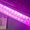
ではちょっと点灯をば
無事にLCDのLEDバックライトの調光が出来た様で。
バックライトコントロールピンが出ているLCDなら簡単ですね
※LCDに表示させているのはBoomer/TFT_eSPIライブラリに入っていたサンプル 'Boing’ ball demo です。
まとめ
LEDを扱う場合、PWMで出力した方が扱いやすいみたいですね。
LEDはダイオードですから、既定の電圧にならないと電流が流れないわけで・・・
DACで調光を行う場合、調光するLEDがどの電圧から点灯し出すのかをいちいち調べないといけない。
規定電圧をマシンガンの様に打ち出すPWMであれば、必ず点灯し明るさ調整はデューティ比でコントロールできるというわけです。
なるほどPWMとアナログ(?)出力の特性の違いがよく判りました。
当初はLCDを調光しようとしただけなのに、ガッツリと横道に逸れてしまい
動画編集ソフトというのも初めて使いました・・・
実験君もまた楽しいのですけれど、時間くいますね( ノД`)

 https://github.com/espressif/arduino-esp32/blob/master/cores...
 https://github.com/espressif/arduino-esp32/blob/master/cores...




ディスカッション
コメント一覧
まだ、コメントがありません