ESP32でSPI接続1.3インチ液晶モジュールを使ってみる
前回は初マイコンLCDにチャレンジして負けましたからね、、
今回のお客様はこれ。
TZT TFTディスプレイ 1.3inch SPI接続ボード
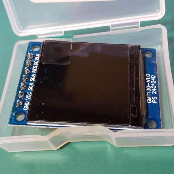
前回のブツと同時に買っておいて、ずっと眠らせていた品物。
こいつなら大丈夫です。
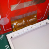
なにしろ裏に
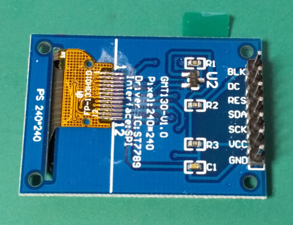
ドライバーICがちゃんと書いてあるんですから!
今回のドライバICは、ST7789様の様です。
なんかIPSって書いてあるので、IPS液晶なのかしら。
購入ページにはTFTって書いてあったのに・・・まぁいいや
こんなに小さいのに、解像度は240×240もあるみたいです。
LCDモジュールとの接続
というわけで、早速これを
・・・どうやって接続しましょうかね。
SPIという事は、CS、SCLK、MOSI、MISOを使うんだと思うんですが、このボードはなんかシルク印刷の文字が違う。
BLK、DC、RES、SDA、SCK、VCC、GND の7ピン。
VCCとGNDはとりあえず置いといて、BLKはなんかバックライトっぽい
すると、DC、RES、SDA、SCK。
受け取る専門だと思うので液晶側にMOSIは無いとして、SCKはクロックでしょう。
RESはリセット?するとあと2本
DCは何だろな、、、
SDAは、なんかデータ線っぽいか
と思って販売元のページを見たら書いてありました。
| Pins | Desc |
|---|---|
| GND | Power Gtound |
| VCC | 3.3V-5V(DC) |
| SCL | SPI clock line |
| SDA | SPI data line |
| RES | Reset interface |
| DC | SPI data / command selection |
| CS | Chip select(0.96inch only) |
| BLK | Backlight control, default floating, low level off |
んん?
チップセレクトが無いんだってさ
大丈夫かしら・・・
とりあえずザクザク繋いで、あとはマイコンにお任せしよう( ノД`)
こういうのはやってみるのが肝心なんですよきっと
BLK、DC、RES、SDA、SCK、VCC、GND の接続を
| NodeMCU-32S | 1.3inch LCD | Desc |
|---|---|---|
| 21 | BLK | Backlight control, default floating, low level off |
| 16 | DC | SPI data / command selection |
| 17 | RES | Reset interface |
| 23 | SDA | SPI data line |
| 18 | SCL | SPI clock line |
| 3.3V | VCC | 3.3V-5V(DC) |
| GND | GND | Power Gtound |
| – | CS | Chip select(0.96inch only) |
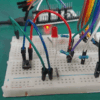
ひとまず動作確認はこんな感じの接続で、、
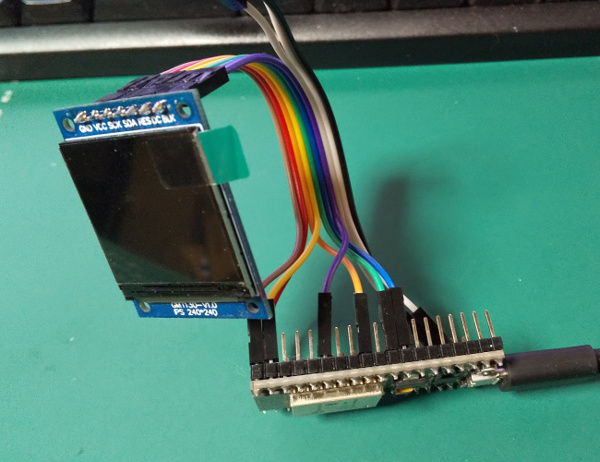
今回もそびえ立つ様な空中配線ですね
植物系モンスターみたいな佇まい。
LCDライブラリと設定
さてこれを動かすライブラリをどうしようかと。
PlatformIOからST7789で検索すると、現在一番ダウンロード数が多そうなコレを使ってみる事にします。
なんかePaperまで手を出している様ですので、長く使わせていただけそうな感じです。
とりあえずPlatformIOからこのライブラリを導入しまして、、、
ざっとライブラリの構成を眺めてみると、「/TFT_eSPI/tree/master/User_Setups」というディレクトリがあり、なんかいろんなコントローラの設定サンプルが並んでいました。
まさにこのLCDの240×240サンプルもある様で。
ソレっぽいこの「Setup24_ST7789.h」テンプレを使わせていただきます。
説明書きに、モジュールをアップデートとかするとセットアップファイルが上書きされるから、「TFT_eSPI_Setups」とかディレクトリ作って置いとくといいよ!とか書いてあるので、ディレクトリを作ってそこに置きます。
\src\TFT_eSPI_Setups\Setup24_ST7789.h みたいな感じで。
※VSCode PlatformIOの場合
そしたらライブラリの「User_Setup_Select.h」にあるincludeパスを書き換えて、先ほど設置したコンフィグファイルを読ませる様にします。(/TFT_eSPI/User_Setup_Select.h)
ただ、ここでライブラリからの相対パスの記述がなんか上手くいきませんでしたので、、、
//#include <User_Setup.h>           // Default setup is root library folder
//#include <../TFT_eSPI_Setups/Setup24_ST7789.h>
#include <D:\VSCodeProjects\PlatformIO\UsingLCD_ST7789\src\TFT_eSPI_Setups\Setup24_ST7789.h>こんな感じでセパレータは¥(\)のフルパスで記述。いやん、、ディレクトリ構造がバレちゃう
ううん、釈然としませんので今度調べておきます・・・
さて、このコピったセットアップファイルに結線した情報を書き込んでおきます。
デフォルトのIOピンの設定はこんな感じになっていました。
/TFT_eSPI_Setups/Setup24_ST7789.h(編集前)
// Generic ESP32 setup
//#define TFT_MISO 19
//#define TFT_MOSI 23
//#define TFT_SCLK 18
//#define TFT_CS    -1 // Not connected
//#define TFT_DC    2
//#define TFT_RST   4  // Connect reset to ensure display initialises

// For NodeMCU - use pin numbers in the form PIN_Dx where Dx is the NodeMCU pin designation
#define TFT_CS   -1      // Define as not used
#define TFT_DC   PIN_D1  // Data Command control pin
#define TFT_RST  PIN_D4  // TFT reset pin (could connect to NodeMCU RST, see next line)
//#define TFT_RST  -1    // TFT reset pin connect to NodeMCU RST, must also then add 10K pull down to TFT SCK
なんかNodeMCU用の設定のサンプルがコメント付きであるんですが、、
リセットピンとマイコンのリセットピンを繋いで、クロックの線をプルダウンしろと・・・?
プルダウンの方はなんかクロック信号を安定させる目的でしょうかね。
近くで携帯やラジオを使ったら誤動作するかもしれません(ぇ
めんどくさそうなのでとりあえずコメントアウトして勝手に設定(ぇ
/TFT_eSPI_Setups/Setup24_ST7789.h(編集後)
// Generic ESP32 setup
#define TFT_MISO -1		// misoは使わないぽ
#define TFT_MOSI 23
#define TFT_SCLK 18
#define TFT_CS   -1		// Not connected
#define TFT_DC   16		// データ用
#define TFT_RST  17		// リセット
#define TFT_BL   21		// バックライト

// For NodeMCU - use pin numbers in the form PIN_Dx where Dx is the NodeMCU pin designation
//#define TFT_CS   -1      // Define as not used
//#define TFT_DC   PIN_D1  // Data Command control pin
//#define TFT_RST  PIN_D4  // TFT reset pin (could connect to NodeMCU RST, see next line)
////#define TFT_RST  -1    // TFT reset pin connect to NodeMCU RST, must also then add 10K pull down to TFT SCK
NodeMCU用設定はとりあえずガン無視で、、
主に信号線ですから間違ってても多分大丈夫ですキット。
ライブラリサンプルプログラムの実行:その1
さてライブラリのサンプル「examples」の中に「Test and diagnostics」というディレクトリが。
そこに診断プログラムっぽい気がするネーミングの「Read_User_Setup.ino」というのがありましたので、これをコピってきて実行してみます。
/TFT_eSPI/examples/Test and diagnostics/Read_User_Setup/Read_User_Setup.ino
実行時のシリアルモニタの出力がこちら。
[code]
TFT_eSPI ver = 2.3.2
Processor    = ESP32
Frequency    = 240MHz
Transactions = Yes
Interface    = SPI
Display driver = 7789
Display width  = 240
Display height = 240

MOSI    = GPIO 23
MISO    = GPIO 19
SCK     = GPIO 18
TFT_DC   = GPIO 16
TFT_RST  = GPIO 17

TFT_BL           = GPIO 21
TFT_BACKLIGHT_ON = HIGH

Font GLCD   loaded
Font 2      loaded
Font 4      loaded
Font 6      loaded
Font 7      loaded
Font 8      loaded
Smooth font enabled

Display SPI frequency = 40.00
[/code]
上手く動いた様ですね。
このツールはつまり設定が正しく読まれてるかどうかを確認するためのツールの様で。。。
Display driver も 7789 が読み込まれ、液晶サイズも 240×240 の指定ができましたよ的な。
重要な事ではありますが、なんかつまらないので他のスケッチを試してみます。(ぇ
ライブラリサンプルプログラムの実行:その2
これなんかヨサゲですね。
「Viewport_graphicstest.ino」
/TFT_eSPI/examples/Generic/Viewport_graphicstest/Viewport_graphicstest.ino
名前的に。
これをコピってきまして、、
いつからかPlatformIOではプロトタイプを書けとエラーが沢山出るので、面倒ですが使っている関数を全て書き出します。
シリアルの速度を変えて、あとは画面サイズはなんか「setViewport()」でやるみたいですので、240×240に合わせて変えました。
setViewportは2か所あります。
変更点はこれだけ。
スケッチはこんな感じ。
/*
 This sketch demonstrates the Adafruit graphicstest sketch running in a
 viewport (aka window) within the TFT screen area. To do this line 37 has
 been added. Line 39 draws a frame outside the viewport.

 This sketch uses the GLCD font (font 1) only.

 Make sure all the display driver and pin comnenctions are correct by
 editting the User_Setup.h file in the TFT_eSPI library folder.

 #########################################################################
 ###### DON'T FORGET TO UPDATE THE User_Setup.h FILE IN THE LIBRARY ######
 #########################################################################
*/


#include "SPI.h"
#include "TFT_eSPI.h"

TFT_eSPI tft = TFT_eSPI();

unsigned long total = 0;
unsigned long tn = 0;

// プロトタイプを追加
unsigned long testFillScreen();
unsigned long testText();
unsigned long testLines(uint16_t);
unsigned long testFastLines(uint16_t, uint16_t);
unsigned long testRects(uint16_t);
unsigned long testFilledRects(uint16_t, uint16_t);
unsigned long testFilledCircles(uint8_t, uint16_t);
unsigned long testCircles(uint8_t, uint16_t);
unsigned long testTriangles();
unsigned long testFilledTriangles();
unsigned long testRoundRects();
unsigned long testFilledRoundRects();

void setup() {
//  Serial.begin(9600);
  // シリアルを自分の環境に合わせて設定
  Serial.begin(115200);
  while (!Serial);

  Serial.println(""); Serial.println("");
  Serial.println("TFT_eSPI library test!");

  tft.init();

  tn = micros();
  tft.fillScreen(TFT_BLACK);

  // Create a viewport 220 x 300 pixels
//  tft.setViewport(10,10,220,300);
  // 240x240に合わせて設定
  tft.setViewport(10,10,220,220);

  tft.frameViewport(TFT_RED, -1); // 1 pixel wide frame around viewport

  yield(); Serial.println(F("Benchmark                Time (microseconds)"));

  yield(); Serial.print(F("Screen fill              "));
  yield(); Serial.println(testFillScreen());
  //total+=testFillScreen();
  //delay(500);

  yield(); Serial.print(F("Text                     "));
  yield(); Serial.println(testText());
  //total+=testText();
  //delay(3000);

  yield(); Serial.print(F("Lines                    "));
  yield(); Serial.println(testLines(TFT_CYAN));
  //total+=testLines(TFT_CYAN);
  //delay(500);

  yield(); Serial.print(F("Horiz/Vert Lines         "));
  yield(); Serial.println(testFastLines(TFT_RED, TFT_BLUE));
  //total+=testFastLines(TFT_RED, TFT_BLUE);
  //delay(500);

  yield(); Serial.print(F("Rectangles (outline)     "));
  yield(); Serial.println(testRects(TFT_GREEN));
  //total+=testRects(TFT_GREEN);
  //delay(500);

  yield(); Serial.print(F("Rectangles (filled)      "));
  yield(); Serial.println(testFilledRects(TFT_YELLOW, TFT_MAGENTA));
  //total+=testFilledRects(TFT_YELLOW, TFT_MAGENTA);
  //delay(500);

  yield(); Serial.print(F("Circles (filled)         "));
  yield(); Serial.println(testFilledCircles(10, TFT_MAGENTA));
  //total+= testFilledCircles(10, TFT_MAGENTA);

  yield(); Serial.print(F("Circles (outline)        "));
  yield(); Serial.println(testCircles(10, TFT_WHITE));
  //total+=testCircles(10, TFT_WHITE);
  //delay(500);

  yield(); Serial.print(F("Triangles (outline)      "));
  yield(); Serial.println(testTriangles());
  //total+=testTriangles();
  //delay(500);

  yield(); Serial.print(F("Triangles (filled)       "));
  yield(); Serial.println(testFilledTriangles());
  //total += testFilledTriangles();
  //delay(500);

  yield(); Serial.print(F("Rounded rects (outline)  "));
  yield(); Serial.println(testRoundRects());
  //total+=testRoundRects();
  //delay(500);

  yield(); Serial.print(F("Rounded rects (filled)   "));
  yield(); Serial.println(testFilledRoundRects());
  //total+=testFilledRoundRects();
  //delay(500);

  yield(); Serial.println(F("Done!")); yield();
  //Serial.print(F("Total = ")); Serial.println(total);

  //yield();Serial.println(millis()-tn);
}

void loop(void) {
  for (uint8_t rotation = 0; rotation < 4; rotation++) {
    tft.setRotation(rotation);
    tft.resetViewport();       // reset viewport to whole screen
    tft.fillScreen(TFT_BLACK); // so it can be cleared

    // Create a viewport 220 x 300 pixels
//    tft.setViewport(10,10,220,300);
	// 240x240に合わせて設定
	tft.setViewport(10,10,220,220);
    tft.frameViewport(TFT_RED, -1); // 1 pixel wide frame around viewport

    testText();
    delay(2000);
  }
}


unsigned long testFillScreen() {
  unsigned long start = micros();
  tft.fillScreen(TFT_BLACK);
  tft.fillScreen(TFT_RED);
  tft.fillScreen(TFT_GREEN);
  tft.fillScreen(TFT_BLUE);
  tft.fillScreen(TFT_BLACK);
  return micros() - start;
}

unsigned long testText() {
  tft.fillScreen(TFT_BLACK);
  unsigned long start = micros();
  tft.setCursor(0, 0);
  tft.setTextColor(TFT_WHITE);  tft.setTextSize(1);
  tft.println("Hello World!");
  tft.setTextColor(TFT_YELLOW); tft.setTextSize(2);
  tft.println(1234.56);
  tft.setTextColor(TFT_RED);    tft.setTextSize(3);
  tft.println(0xDEADBEEF, HEX);
  tft.println();
  tft.setTextColor(TFT_GREEN);
  tft.setTextSize(5);
  tft.println("Groop");
  tft.setTextSize(2);
  tft.println("I implore thee,");
  //tft.setTextColor(TFT_GREEN,TFT_BLACK);
  tft.setTextSize(1);
  tft.println("my foonting turlingdromes.");
  tft.println("And hooptiously drangle me");
  tft.println("with crinkly bindlewurdles,");
  tft.println("Or I will rend thee");
  tft.println("in the gobberwarts");
  tft.println("with my blurglecruncheon,");
  tft.println("see if I don't!");
  return micros() - start;
}

unsigned long testLines(uint16_t color) {
  unsigned long start, t;
  int           x1, y1, x2, y2,
                w = tft.width(),
                h = tft.height();

  tft.fillScreen(TFT_BLACK);

  x1 = y1 = 0;
  y2    = h - 1;
  start = micros();
  for (x2 = 0; x2 < w; x2 += 6) tft.drawLine(x1, y1, x2, y2, color);
  x2    = w - 1;
  for (y2 = 0; y2 < h; y2 += 6) tft.drawLine(x1, y1, x2, y2, color);
  t     = micros() - start; // fillScreen doesn't count against timing

  tft.fillScreen(TFT_BLACK);

  x1    = w - 1;
  y1    = 0;
  y2    = h - 1;
  start = micros();
  for (x2 = 0; x2 < w; x2 += 6) tft.drawLine(x1, y1, x2, y2, color);
  x2    = 0;
  for (y2 = 0; y2 < h; y2 += 6) tft.drawLine(x1, y1, x2, y2, color);
  t    += micros() - start;

  tft.fillScreen(TFT_BLACK);

  x1    = 0;
  y1    = h - 1;
  y2    = 0;
  start = micros();
  for (x2 = 0; x2 < w; x2 += 6) tft.drawLine(x1, y1, x2, y2, color);
  x2    = w - 1;
  for (y2 = 0; y2 < h; y2 += 6) tft.drawLine(x1, y1, x2, y2, color);
  t    += micros() - start;

  tft.fillScreen(TFT_BLACK);

  x1    = w - 1;
  y1    = h - 1;
  y2    = 0;
  start = micros();
  for (x2 = 0; x2 < w; x2 += 6) tft.drawLine(x1, y1, x2, y2, color);
  x2    = 0;
  for (y2 = 0; y2 < h; y2 += 6) tft.drawLine(x1, y1, x2, y2, color);

  return micros() - start;
}

unsigned long testFastLines(uint16_t color1, uint16_t color2) {
  unsigned long start;
  int           x, y, w = tft.width(), h = tft.height();

  tft.fillScreen(TFT_BLACK);
  start = micros();
  for (y = 0; y < h; y += 5) tft.drawFastHLine(0, y, w, color1);
  for (x = 0; x < w; x += 5) tft.drawFastVLine(x, 0, h, color2);

  return micros() - start;
}

unsigned long testRects(uint16_t color) {
  unsigned long start;
  int           n, i, i2,
                cx = tft.width()  / 2,
                cy = tft.height() / 2;

  tft.fillScreen(TFT_BLACK);
  n     = min(tft.width(), tft.height());
  start = micros();
  for (i = 2; i < n; i += 6) {
    i2 = i / 2;
    tft.drawRect(cx - i2, cy - i2, i, i, color);
  }

  return micros() - start;
}

unsigned long testFilledRects(uint16_t color1, uint16_t color2) {
  unsigned long start, t = 0;
  int           n, i, i2,
                cx = tft.width()  / 2 - 1,
                cy = tft.height() / 2 - 1;

  tft.fillScreen(TFT_BLACK);
  n = min(tft.width(), tft.height());
  for (i = n - 1; i > 0; i -= 6) {
    i2    = i / 2;
    start = micros();
    tft.fillRect(cx - i2, cy - i2, i, i, color1);
    t    += micros() - start;
    // Outlines are not included in timing results
    tft.drawRect(cx - i2, cy - i2, i, i, color2);
  }

  return t;
}

unsigned long testFilledCircles(uint8_t radius, uint16_t color) {
  unsigned long start;
  int x, y, w = tft.width(), h = tft.height(), r2 = radius * 2;

  tft.fillScreen(TFT_BLACK);
  start = micros();
  for (x = radius; x < w; x += r2) {
    for (y = radius; y < h; y += r2) {
      tft.fillCircle(x, y, radius, color);
    }
  }

  return micros() - start;
}

unsigned long testCircles(uint8_t radius, uint16_t color) {
  unsigned long start;
  int           x, y, r2 = radius * 2,
                      w = tft.width()  + radius,
                      h = tft.height() + radius;

  // Screen is not cleared for this one -- this is
  // intentional and does not affect the reported time.
  start = micros();
  for (x = 0; x < w; x += r2) {
    for (y = 0; y < h; y += r2) {
      tft.drawCircle(x, y, radius, color);
    }
  }

  return micros() - start;
}

unsigned long testTriangles() {
  unsigned long start;
  int           n, i, cx = tft.width()  / 2 - 1,
                      cy = tft.height() / 2 - 1;

  tft.fillScreen(TFT_BLACK);
  n     = min(cx, cy);
  start = micros();
  for (i = 0; i < n; i += 5) {
    tft.drawTriangle(
      cx    , cy - i, // peak
      cx - i, cy + i, // bottom left
      cx + i, cy + i, // bottom right
      tft.color565(0, 0, i));
  }

  return micros() - start;
}

unsigned long testFilledTriangles() {
  unsigned long start, t = 0;
  int           i, cx = tft.width()  / 2 - 1,
                   cy = tft.height() / 2 - 1;

  tft.fillScreen(TFT_BLACK);
  start = micros();
  for (i = min(cx, cy); i > 10; i -= 5) {
    start = micros();
    tft.fillTriangle(cx, cy - i, cx - i, cy + i, cx + i, cy + i,
                     tft.color565(0, i, i));
    t += micros() - start;
    tft.drawTriangle(cx, cy - i, cx - i, cy + i, cx + i, cy + i,
                     tft.color565(i, i, 0));
  }

  return t;
}

unsigned long testRoundRects() {
  unsigned long start;
  int           w, i, i2,
                cx = tft.width()  / 2 - 1,
                cy = tft.height() / 2 - 1;

  tft.fillScreen(TFT_BLACK);
  w     = min(tft.width(), tft.height());
  start = micros();
  for (i = 0; i < w; i += 6) {
    i2 = i / 2;
    tft.drawRoundRect(cx - i2, cy - i2, i, i, i / 8, tft.color565(i, 0, 0));
  }

  return micros() - start;
}

unsigned long testFilledRoundRects() {
  unsigned long start;
  int           i, i2,
                cx = tft.width()  / 2 - 1,
                cy = tft.height() / 2 - 1;

  tft.fillScreen(TFT_BLACK);
  start = micros();
  for (i = min(tft.width(), tft.height()); i > 20; i -= 6) {
    i2 = i / 2;
    tft.fillRoundRect(cx - i2, cy - i2, i, i, i / 8, tft.color565(0, i, 0));
  }

  return micros() - start;
}

/***************************************************
  Original Adafruit text:

  This is an example sketch for the Adafruit 2.2" SPI display.
  This library works with the Adafruit 2.2" TFT Breakout w/SD card
  ----> http://www.adafruit.com/products/1480

  Check out the links above for our tutorials and wiring diagrams
  These displays use SPI to communicate, 4 or 5 pins are required to
  interface (RST is optional)
  Adafruit invests time and resources providing this open source code,
  please support Adafruit and open-source hardware by purchasing
  products from Adafruit!

  Written by Limor Fried/Ladyada for Adafruit Industries.
  MIT license, all text above must be included in any redistribution
 ****************************************************/
これをコンパイルして実行してみますと、、
おおなんかカッコイイ。
設定ファイルに「SPI_FREQUENCY 40000000」とありましたので、40Mhzで動いている様です。
シリアルモニタには実行時間が出力されていました。
TFT_eSPI library test!
Benchmark                Time (microseconds)
Screen fill              105067
Text                     14106
Lines                    50207
Horiz/Vert Lines         9398
Rectangles (outline)     8015
Rectangles (filled)      264145
Circles (filled)         30598
Circles (outline)        29450
Triangles (outline)      15919
Triangles (filled)       94309
Rounded rects (outline)  21304
Rounded rects (filled)   270790
Done!
速いのか遅いのかさっぱりですが、、、
描画の仕方とかはexamplesを見て行けばやりたい事は大体できそうな。
このLCDモジュールを使うまでの流れ
さて大体使い方が判ってきましたので、これまでの作業をまとめておきます。
1.SPI接続用ピンとLCDを接続
SCLK、MOSI、DC、RSTの信号線と電源、GNDの合計6本刺さっていれば動きます。
バックライトは制御しなくても勝手に点きます。
チップセレクトも無くていいみたい。わかんないけど。
ESP32の場合はデフォルトでVSPIを使うみたいですので、個別に設定しておかなくても良いピンに接続した方がラクです。
ESP32はマルチプレクサを内蔵しているので、LCDの制御前にリマッピングすれば多分問題なく使えると思います。
2.LCD制御用のライブラリを導入
ドライバICの種類さえ判っていれば、多分他のライブラリでも問題無く動くと思います。
今回は Bodmer / TFT_eSPI ライブラリを使わせて頂きました。
お使いのIDEのライブラリ読み込み機能からLCDドライバICの型式で検索かければ結構出て来ます。
3.ライブラリに接続情報を伝える
コンフィグ設定を作成し、ライブラリ(TFT_eSPI)に読み込ませる設定をします。
特に接続ピンの情報は必須ですので、各ライブラリに合わせて設定してください。
設定方法はライブラリによって・・・ですので、各ライブラリの説明を読んでくださいスマン
4.プログラムの実行
ライブラリには沢山のサンプルが入っていると思いますので、適当にかいつまんで実行してみてください。
大体は、examplesとかいうディレクトリに入ってます。
コピーしてmainに張り付けて、とりあえずコンパイルしてみて、エラーを訂正して、、みたいな手順が早いと思うます。
サンプルのコードと動作を見れば、何がどうなっているのか判ると思います。
前回の2.4インチLCDと比べると、今回は非常に簡単にテストする事ができました。
やっぱりドライバICが判っているというのは素晴らしいですね。
前回は初っ端から冒険させられてしまい・・・( ノД`)
サクサク動いてくれるのは気持ちがいいでする
今後の宿題
なんか順調に使えてしまいまして気分がいいのですが、、
触っていて気になる点がいくつかありました。
- バックライトの制御
- リセットピンの使い方
- SCLKラインにノイズを浴びせたらどうなるか
- VSCode + PlatformIO でプロトタイプを書かなきゃいけないダルい問題
- 動画の手ブレ
普通にちょっと使うだけなら恐らく問題無く動作すると思いますが、気になりますのでその内なんとかしようと思います。

 https://github.com/Bodmer/TFT_eSPI




ディスカッション
コメント一覧
まだ、コメントがありません